Thursday, March 23, 2017

Simply supported or fixed end?

Simply supported or fixed end? This might seem a small decision to make but the engineer's preference on this matter has a major impact in design, economy and appearance of the structure. When to design a beam as simply supported and when to design as fixed end? May this discussion be helpful to my fellow structural designers.


A. Properties of a simply supported beam
  1. There is no bending moment at the supports.
  2. The maximum bending moment is somewhere at the middle of the beam depending on type of loading. 

B. Properties of a beam with both ends fixed
  1. There is bending moment at the supports and at the middle.
  2. The maximum bending moment is at the supports. 
C. Comparison between simply supported and fixed end 
  1. Both has the same shear at support.
  2. Assuming they are to carry the same load, the negative moment at the fixed end is smaller than the positive moment of a simply supported beam.
  3. The point of inflection (zero moment) of a simply supported beam is at the end while the point of inflection of a fixed end beam is a few distance away from the support.
SHEAR AND MOMENT DIAGRAMS OF SIMPLY SUPPORTED AND FIXED END BEAMS
Based on these properties, we can point out the advantages and disadvantages.


A. Simply supported 
  1. Since there is no bending moment at the support, the joint or support is not complicated. We can simply use a shear plate or a clip angle that would resist the shear. 
  2. For rigid supports, beams can be simply laid over with no fixing. This especially applies to temporary structures during construction. Elevated concrete highways are designed as simply supported beams.
  3. The supports of the beam must be rigid. A frame with two columns and a simply supported beam on top must have columns that are moment resisting at the base. 
  4. Simply supported beams are of little help in resisting lateral forces like wind and earthquake.
  5. Simply supported beams are usually thicker due to a big value of maximum bending moment at the center.
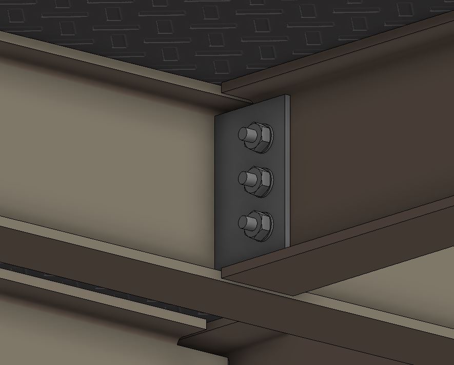
SIMPLE SHEAR CONNECTION
Simple shear connected beams are designed as simple beams

B. Fixed End
  1. Fixed end connections are more rigid. If you are avoiding vibrations and movements at the beam, it is best to design the beam to be fixed at the end. 
  2. Designing a beam in a steel frame as fixed end eliminates the need for moment resisting base. That explains the shape of PEB frame columns that are thicker at the top and thinner at base. That also explains why sometimes, you see only two bolts at the base of the column and see twelve bolts at the joint of the beam and the column.
  3. Fixed end beam connections are moment resisting and therefore more costly than simply supported beam connections.
  4. Fixed end beams are thinner than simply supported beams because, aside from beam center, the ends are also resisting moment.



Friday, February 24, 2017

Minimum Thickness of Concrete Beams and Slabs

One of the common mistakes being committed by some builders, who rely on experience and not on structural calculations, is not observing the minimum thickness or depth of concrete beams and slabs specified in the code.

The code specified minimum thicknesses for different types of support in order to prevent excessive deflection or sagging on site.

NSCP 2010 states the following...


...where L is the length of beam or one way slab and the denominator is the dividing factor. Length in beams is obvious. It is simply the center to center distance of the columns that support the beam. In one way slabs, however, the design length is not the longer side of the slab. It is wiser to design one way slabs considering the shorter side. For example, if you have a 2m x 4m slab, we take the 2m as the length of the slab and design it as a 1m-wide strip beam.

Example: Calculate the minimum thickness of 6m long beam with both ends continuous.

Given:

     Type of Structure:    Beam
     Type of Support:      Both ends continuous
     Length of beam:      6m

Solution:

     Based on the table, the minimum thickness for a beam with both ends continuous is L/21.

Therefore:

     T = L/21
        = 6m / 21
        = 0.286 m or 286 mm

Here is the program that automatically calculates minimum thickness of concrete beams and slabs:
Click here and download the file -> Concrete Beam and Slab Thickness Calculator


Thursday, February 23, 2017

Calculating Maximum Moments of Cantilever Structures

Cantilever is the most daring of all the structures being built. The beauty of a legless front entrance canopy or shed is really stunning. However, wrong calculation of the maximum design moment of the structure may lead to structural failure when ultimate loading condition is reached.

Cantilever shed failed during 4.6 magnitude earthquake. Age might be one of the factors.
For basic cantilevers, earthquake is the main lateral (horizontal) load to be considered in addition to the vertical dead and live loads. Wind might prevail if the structure is too high and the columns are covered with wind resisting panels.

Considering dead load, live load and earthquake loads, here are the load combinations that we need to consider based on NSCP 2010.

1. U = 1.2D +1.6L
2. U = 1.2D + E + 0.5L

I eliminated other combinations which will obviously yield lower result.

From the load diagram below, we can calculate the maximum base moment based on the given equations.


By taking summation of moments at point A...

Mu = X^2/2(1.2D + 1.6L)                -> Equation 1
Mu = X^2/2(1.2D + 0.5L) + EH      -> Equation 2

We just need to substitute actual values here to see which equation would yield a greater result. Whichever resulting value is greater, that would be the design moment that should be used.

Example:

Given:
            D = 15kN/m
            L = 6 kN/m
            E = 3kN
            H = 4m
            x = 2m


Solution:
Equation 1     Mu = X^2/2(1.2D + 1.6L)
                             = 2^2/2(1.2*15 + 1.6*6)
                             = 64.2 kNm

Equation 2     Mu = X^2/2(1.2D + 0.5L) + EH
                             = 2^2/2(1.2*15 + 0.5*6) + 3*4
                             = 63 kN

Since Equation 1 yielded greater result, therefore Mu = 64.2 kNm

Assuming we will use a 300 mm x 300 mm concrete column, by applying reinforced concrete design formulas, use:

300 x 300 concrete column with 12-Ø20 RSB.


Wednesday, February 22, 2017

1.4DL + 1.7LL or 1.2DL + 1.6LL ?

For designers like me who were trapped in the past (used to using the old codes), the introduction of new and smaller load factors might be quite hard to accept. In school, we were taught to use 1.4DL + 1.7LL in calculating the ultimate load involving basic dead and live loads. However in the latest NSCP which was released a few years ago, the new load factors are smaller - 1.2DL + 1.6LL.


Below is the table showing the comparison of the new and old codes:

Where:

D = dead load
E = earthquake load 
F = load due to fluids
H = load due to lateral pressure of soil and water in soil
L = live load, except roof live load, including any permitted live load reduction
Lr = roof live load , including any permitted live load reduction
R = rain load on the undef1ected roof
T = self-straining force and effects arising from contraction or expansion resulting from temperature change, shrinkage, moisture change, creep in component materials, movement due to differential settlement, or combinations thereof .
W = load due to wind  pressure
f1 = 1.0 for floors in places of public assembly, for live loads in excess of 4.8 kPa, and for garage live load.
= 0.5 for other live loads
Em = the maximum effect of horizontal and vertical forces as set forth in Section 208.6.1

Which one should we use? In practice, we could use any of these based on engineers discretion because presumably, both of them are safe to apply and there has been lots of studies, researches and experimentation done before structural scientists came up with the numbers. In schools, however, I am not sure if they are using the new code. If the professor says use the new code then use the new code otherwise you'll get the wrong answer because of using the load factors in the old code.

Tuesday, February 21, 2017

Standard Hooks and Minimum Bends

According to NSCP, for a certain bar size, there is a standard minimum size of bend and length of extension.

Here is the easy tabular and graphical interpretation of the code regarding bends and hooks.


The table below shows the numerical values of the table above.


Tuesday, May 24, 2016

Determining weight without using weighing scales

Many people would think of using weighing scales when they are asked to determine the weight of something. That may be applicable in small scale but when it comes to heavy structural load computations, we need a mathematical approach and that is what I'll discuss in this blog.


Determining weight by volume


The ratio of mass over volume is called density. The value of density varies among material types. Density is basically weight per volume unit (e.g. kg/cubic meter).

From the relation,

D = M / V

where:
D = Density
M = Mass
V = Volume

we can get the Mass by multiplying the Volume to the known Density.

M = D V

Example:

Determine the total weight of 1.5m diameter by 2.5m high 3mm thick cylindrical water tank at full capacity. The bottom of the tank is 4mm thick and the top cover is 3mm thick.

Solution:

I. Determining the volumes
The first step is to calculate the volumes the tank and the content. The formula for volume of cylinder is

V = πdh

where:

V = Volume
π = pi = 3.1416
h = height

A. Total volume
VT = π(1.5m)(2.5m)
VT = 11.781 cubic meters

B. Volume of water
VW = π(1.494m)(2.493m)
VW = 11.701 cubic meters

C. Volume of tank
Vtank = VT - VW
Vtank = 0.08 cubic meters


I. Determining the weights
To get the weights of water and tank, multiply the volume by the density. The density of water is 1000 kg / cu.m and the density of steel is 7850 kg / cu.m.

A. Weight of Water
Ww = VW x 1000 kg/cu.m
Ww = 11.701cu.m x 1000kg/cu.m
Ww = 11701 kg or 11.7 tons

B. Weight of tank
Wtank = Vtank x 7850 kg/cu.m
Wtank = 0.08 cu.m x  7850 kg/cu.m
Wtank = 638 kg or 0.638 tons

C. Total weight
WT = Ww + Wtank
WT = 11.701 tons + .638 ton
WT = 12.339 tons